Table of Contents
- 1. Introduction
- 2. Fundamentals of Deep Drawing
- 3. Common Issues in Deep Drawing: Wrinkling and Tearing
- 4. The Science Behind Wrinkling and Tearing
- 5. Practical Strategies to Prevent Wrinkling
- 6. Practical Strategies to Prevent Tearing
- 7. Advanced Techniques and Technologies
- 8. Troubleshooting Common Stamping Process Issues
- 9. Best Practices for Stamping Process Optimization
- 10. Conclusion
1. Introduction
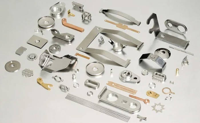
The deep drawing stamping process is a cornerstone of modern manufacturing, responsible for producing a vast array of components, from automotive body panels and kitchen sinks to beverage cans and battery casings. It is a highly efficient method for transforming a flat sheet of metal, known as a blank, into a three-dimensional hollow shape without seams or joints. The success of this process hinges on achieving a final product that meets precise geometric specifications and maintains its structural integrity.
However, the path from a flat blank to a perfect part is fraught with challenges. Two of the most persistent and costly defects are wrinkling and tearing. These issues not only compromise the aesthetic quality and functional performance of the part but also lead to material waste, increased production costs, and significant downtime. For anyone involved in the stamping process, from engineers and tool designers to machine operators, understanding the root causes of these defects is paramount.
This article delves into the science behind the deep drawing process to address these common concerns. We will explore the fundamental mechanics of deep drawing, analyze the scientific principles governing material flow, and provide practical, actionable strategies to prevent wrinkling and tearing. By bridging the gap between scientific theory and shop-floor application, this guide aims to empower stamping process users to optimize their operations, enhance product quality, and improve overall manufacturing efficiency.
2. Fundamentals of Deep Drawing
Definition and Explanation of Deep Drawing
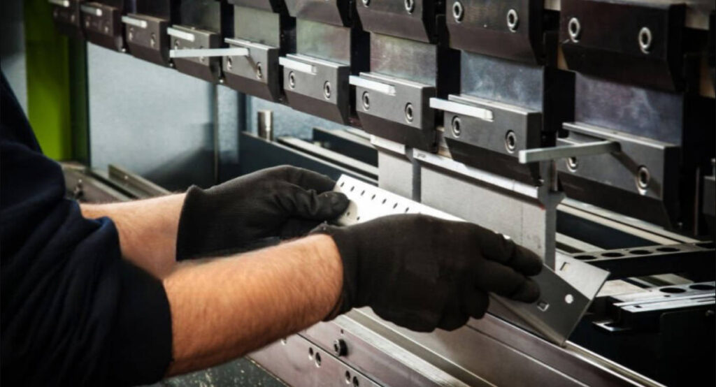
Deep drawing is a sheet metal forming process where a flat sheet metal blank is radially drawn into a forming die by the mechanical action of a punch. It is considered “deep” drawing when the depth of the drawn part is equal to or greater than its diameter. The core principle of deep drawing involves controlled plastic deformation, where the material is stretched and compressed simultaneously to form the desired shape without fracture. The process reshapes the material by forcing it to flow into the die cavity, resulting in a seamless, hollow component.
Key Components: Punch, Die, and Blank Holder
The deep drawing operation is carried out using a specialized set of tools, each playing a critical role in controlling the material flow.
- Punch: This is the male component that moves downward, pushing the sheet metal blank into the die cavity. The shape of the punch nose and its corner radius are critical factors that influence stress concentration and the risk of tearing.
- Die: This is the female component that contains the cavity defining the final shape of the part. The die profile radius is crucial for allowing the material to flow smoothly from the flange into the die, minimizing frictional resistance.
- Blank Holder (or Binder): The blank holder applies a controlled downward pressure on the periphery of the blank (the flange area). The primary function of the blank holder is to control the flow of material into the die, preventing the formation of wrinkles in the flange. The amount of force it applies, known as the Blank Holder Force (BHF), is one of the most critical process parameters.
Materials Commonly Used in Deep Drawing
The suitability of a material for deep drawing is determined by its formability—its ability to undergo plastic deformation without failing. Materials with high ductility and good tensile strength are preferred.
- Steel: Low-carbon steels, such as Drawing Quality (DQ) and Deep Drawing Quality (DDQ) steels, are widely used due to their excellent formability and cost-effectiveness. Stainless steels are also used for applications requiring corrosion resistance, though they are generally more difficult to draw.
- Aluminum: Aluminum alloys are popular in the automotive and aerospace industries for their high strength-to-weight ratio. However, they typically have lower formability than steel and require careful control of process parameters like lubrication and temperature.
- Copper and Brass: These materials exhibit excellent ductility and are easily drawn, making them ideal for producing electrical components, ammunition casings, and decorative items.
3. Common Issues in Deep Drawing: Wrinkling and Tearing
Wrinkling and tearing are the two most prevalent defects that plague deep drawing operations. Understanding their distinct causes and characteristics is the first step toward prevention.
Explanation of Wrinkling: Causes and Visual Characteristics
Wrinkling is a common deep drawing defect characterized by the formation of wave-like undulations on the flange or wall of a drawn part. These wrinkles occur due to excessive compressive stresses in the circumferential direction of the blank’s flange as its diameter is reduced. When the compressive stress exceeds the material’s ability to resist buckling, the material folds over on itself.
- Causes: The primary cause is insufficient Blank Holder Force (BHF). If the BHF is too low, it cannot adequately restrain the material in the flange, allowing it to buckle under compression. Other contributing factors include improper lubrication, incorrect die geometry, and poor material properties.
- Visual Characteristics: Wrinkles typically appear as a series of evenly or unevenly spaced folds or waves. They can be classified as flange wrinkles (occurring on the part’s flange) or wall wrinkles (propagating from the flange into the vertical wall of the part).
Explanation of Tearing: Causes and Failure Mechanisms
Tearing, also known as fracture or splitting, occurs when the tensile stress in the sheet metal exceeds its ultimate tensile strength (UTS). This results in a catastrophic failure, rendering the part unusable. Tearing most often initiates in areas of high stress concentration, such as the punch nose radius or the vertical wall of the cup.
- Causes: The main cause is excessive tensile stress. This can be induced by several factors, including:
- Excessive Blank Holder Force (BHF), which restricts material flow and increases the force needed to pull the material into the die.
- A high draw ratio, which demands too much material deformation in a single step.
- Sharp radii on the punch or die, which create stress concentration points.
- Inadequate lubrication, leading to high friction that resists material flow.
- Failure Mechanisms: Tearing can manifest as a vertical split along the wall of the part, a fracture at the bottom corner (punch nose radius), or a crack initiating from a small surface defect in the material.
Impact of These Defects on Product Performance and Manufacturing Efficiency
Both wrinkling and tearing have severe consequences. Wrinkled parts may not fit correctly in assemblies and often possess diminished structural strength. Tearing results in immediate scrap. These defects lead to lower production yields, increased material costs, unplanned machine downtime for die adjustments, and potential damage to expensive tooling.
4. The Science Behind Wrinkling and Tearing
Preventing defects requires understanding the interplay between material properties, stresses, and process parameters.
Material Properties Affecting Deep Drawing
The intrinsic properties of the sheet metal are fundamental to its behavior during deep drawing.
| Material Property | Description | Impact on Deep Drawing |
|---|---|---|
| Ductility (n-value) | The material’s ability to deform plastically without fracturing. The strain-hardening exponent (n-value) is a key indicator. | A higher n-value allows for more uniform stretching and distribution of strain, reducing the risk of localized thinning and tearing. |
| Anisotropy (r-value) | The variation of material properties with direction. The plastic strain ratio (r-value) measures resistance to thinning. | A high average r-value indicates good resistance to thinning. A low planar anisotropy (Δr) value ensures uniform material flow, preventing “earing” (the formation of wavy edges). |
| Yield Strength (YS) | The stress at which the material begins to deform plastically. | Lower yield strength makes it easier to initiate forming, but the material must have sufficient work-hardening capacity to prevent tearing. |
| Ultimate Tensile Strength (UTS) | The maximum stress the material can withstand before it begins to fracture. | The gap between YS and UTS (the work-hardening window) should be large enough to allow for significant deformation without failure. |
Role of Stress and Strain Distribution in the Blank
During deep drawing, a complex state of stress and strain develops across the blank.
- Flange Area: The material in the flange is subjected to radial tensile stress (as it’s pulled into the die) and circumferential compressive stress (as the diameter decreases). It is the balance between this radial tension and circumferential compression that dictates whether the material flows smoothly or wrinkles.
- Die Radius: The material flowing over the die radius undergoes bending and unbending, which induces significant tensile and compressive stresses.
- Sidewall: The material in the vertical sidewall is primarily under uniaxial tensile stress from the force exerted by the punch. This is the area most susceptible to thinning and tearing.
- Punch Bottom: The area in direct contact with the punch face experiences biaxial tension (stretching).
Influence of Friction and Lubrication on Material Flow
Friction plays a dual role in deep drawing. Some friction is necessary between the punch and the blank to help stretch the material, but excessive friction between the blank and the die or blank holder is detrimental.
Proper lubrication is critical for reducing friction at the die and blank holder interfaces, allowing the material to flow smoothly into the die cavity. A lack of lubrication increases the drawing force required, promoting tearing. Conversely, too much lubricant can become trapped and cause surface defects. The choice of lubricant depends on the material, severity of the draw, and production speed.
Effect of Blank Holder Force and Draw Ratio
- Blank Holder Force (BHF): As discussed, BHF is the most critical adjustable parameter.
- Too Low BHF: Leads to wrinkling due to uncontrolled material compression.
- Too High BHF: Restricts material flow, increasing friction and tensile stress in the sidewall, which leads to tearing.
- Draw Ratio (DR): The draw ratio is the ratio of the initial blank diameter (D) to the punch diameter (d). The Limiting Draw Ratio (LDR) is the maximum draw ratio that can be achieved in a single operation without tearing. Attempting a draw with a ratio exceeding the material’s LDR will almost certainly result in failure.
5. Practical Strategies to Prevent Wrinkling
Optimizing Blank Holder Force: Balancing Pressure to Avoid Wrinkles
The most effective way to combat wrinkling is through precise control of the BHF. The ideal BHF is not a single value but rather a window. Start with a low BHF and gradually increase it in small increments with each stroke until the wrinkles disappear. Modern presses allow for a variable BHF profile, applying higher pressure at the beginning of the stroke when the flange is largest and more prone to wrinkling, and then reducing it as the draw progresses.
Selecting Appropriate Lubricants to Reduce Friction
Choose a lubricant with the correct viscosity and additives for the specific application. High-pressure lubricants are essential for severe draws on materials like stainless steel and aluminum. Application methods are also important; ensure a uniform, consistent film of lubricant is applied to the blank. Automated roller or spray systems are superior to manual application.
Blank Design Considerations: Shape, Size, and Thickness
The initial blank shape can be optimized to control material flow. For non-symmetrical parts, developing a blank shape that is not a perfect circle can provide extra material in areas that undergo severe stretching and less material where it is prone to wrinkling. Finite Element Analysis (FEA) is an invaluable tool for simulating and optimizing blank shape. Thicker blanks are inherently more resistant to buckling and wrinkling.
Tooling Geometry Adjustments to Improve Material Flow
Smooth, generous radii on the die and punch are crucial. A larger die radius encourages material to flow into the cavity, reducing the drawing force. If wrinkles are forming on the wall, it might indicate that the clearance between the punch and the die is too large, allowing the material to buckle after it has passed over the die radius.
6. Practical Strategies to Prevent Tearing
Controlling Draw Depth and Draw Ratio to Avoid Excessive Thinning
The most direct way to prevent tearing is to reduce the severity of the operation. If tearing occurs, the first parameter to check is the draw ratio. If it exceeds the material’s LDR, the part must be redesigned, or the process must be broken down into multiple stages.
| Material | Typical Limiting Draw Ratio (LDR) |
|---|---|
| Deep Drawing Steel | 2.0 – 2.2 |
| Stainless Steel (304) | 1.9 – 2.1 |
| Aluminum (Alloy 3003) | 1.8 – 2.0 |
| Copper | 2.1 – 2.3 |
Material Selection for Improved Formability
If tearing persists despite process optimization, the material itself may be the issue. Switching to a grade with better deep drawing properties (e.g., from DQ to DDQ steel) can solve the problem. Look for materials with a higher n-value and r-value. Always ensure incoming material meets specifications through quality control checks.
Adjusting Punch Speed and Temperature Conditions
- Punch Speed: Slower punch speeds generally improve formability. A slower draw allows more time for stress to distribute evenly and reduces the heat generated by friction. Modern servo presses offer full control over the punch speed throughout the stroke, allowing for optimization.
- Temperature: For some difficult-to-form materials like magnesium or certain aluminum alloys, “warm drawing” (heating the blank to a specific temperature) can significantly increase ductility and prevent tearing.
Using Multi-Stage Drawing for Complex Shapes
For parts with a high draw ratio or complex geometry, attempting to form them in a single step is often impossible. A multi-stage drawing process, using a series of dies to incrementally shape the part, is the standard solution. This involves intermediate annealing steps between draws to relieve work hardening and restore the material’s ductility.
7. Advanced Techniques and Technologies
Use of Finite Element Analysis (FEA) for Process Simulation
FEA software allows engineers to simulate the entire deep drawing process digitally before any physical tooling is made. This powerful tool can predict material flow, stress and strain distributions, and the likelihood of defects like wrinkling and tearing. By running virtual trials, designers can optimize tooling geometry, BHF, blank shape, and other parameters, dramatically reducing the time and cost of physical tool development and tryout.
Adaptive Blank Holder Force Control Systems
Modern hydraulic and servo presses can be equipped with adaptive control systems. These systems use sensors to monitor the drawing process in real-time and automatically adjust the BHF during the stroke. For example, if sensors detect the start of wrinkling, the system can instantly increase the force. This closed-loop control allows for a much wider processing window and can compensate for minor variations in material properties or lubrication.
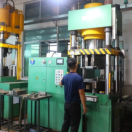
Emerging Trends: Servo Presses and Real-Time Monitoring
Servo-driven presses represent a significant advancement over traditional mechanical or hydraulic presses. Their key advantage is the ability to program a fully customized motion profile for the press slide (punch). The speed and position of the punch can be controlled with extreme precision throughout the stroke. For instance, the punch can be slowed down as it contacts the blank, accelerated during the draw, and even dwelled at the bottom of the stroke. This level of control enables the optimization of material flow to an extent not previously possible, significantly expanding the capabilities of the deep drawing process.
8. Troubleshooting Common Stamping Process Issues
How to Identify Early Signs of Wrinkling and Tearing
Early detection is key to minimizing scrap.
- Wrinkling: Look for slight “waviness” or “puckering” on the flange of the part as it is being formed. These are the precursors to full-blown wrinkles.
- Tearing: Monitor the drawing force. A sudden spike in the force tonnage is a strong indicator that the material is thinning excessively and is about to tear. Polished witness lines or “bright spots” on the part’s surface indicate areas of high friction and potential tearing.
Step-by-Step Diagnostic Process for Defect Analysis
- Isolate the Defect: Clearly identify the type of defect (wrinkle or tear) and its exact location on the part.
- Check the Basics: Verify that the correct material is being used, the lubricant is being applied correctly, and the press settings (BHF, speed) match the process sheet.
- Analyze the Tooling: Inspect the punch and die for wear, chipping, or galling (material pickup). Measure critical radii and clearances.
- Review Process Parameters:
- If Wrinkling: Incrementally increase the BHF. Check for uniform pressure distribution.
- If Tearing: Incrementally decrease the BHF. Reduce the punch speed. Improve lubrication.
- Examine the Material: Test the mechanical properties of the sheet metal coil to ensure it meets specifications.
Corrective Actions for Common Stamping Process Challenges
- Challenge: Wrinkles in the flange.
Action: Increase BHF. Use draw beads in the die to add restraint. - Challenge: Tearing at the punch nose radius.
Action: Increase the punch radius. Decrease the BHF. Improve lubrication in that specific area. - Challenge: Vertical wall tears.
Action: Decrease BHF. Reduce draw ratio. Switch to a material with better formability. - Challenge: Earing on the top edge of the cup.
Action: This is caused by material anisotropy. A material with a lower Δr value is needed. Alternatively, the blank shape can be modified to compensate.
9. Best Practices for Stamping Process Optimization
Importance of Consistent Material Quality and Inspection
Your process is only as good as your raw materials. Establish a robust incoming material inspection program. This should include checking certifications and performing sample tests for thickness, hardness, and tensile properties. Consistency from coil to coil is essential for a stable, repeatable process.
Regular Maintenance of Tooling and Equipment
Tooling wears over time. Die radii can become smaller, and surfaces can become galled. Implement a proactive maintenance schedule for cleaning, polishing, and inspecting all tooling components. Worn components should be repaired or replaced before they begin to cause defects. The press itself should also be regularly maintained to ensure accuracy and repeatability.
Training Operators to Recognize and Address Defects
Operators are the first line of defense against defects. Train them to recognize the early warning signs of wrinkling and tearing and empower them to make approved adjustments to parameters like BHF or lubrication. A well-trained operator can prevent the production of large quantities of scrap parts.
Documentation and Process Control for Repeatable Results
Document every aspect of a successful setup. This includes the material grade, lubricant type and application method, blank size, and all press settings (BHF, speed, shut height). This “recipe” ensures that the process can be quickly and accurately replicated in the future. Implementing Statistical Process Control (SPC) can help monitor key variables and detect process drifts before they lead to defects.
10. Conclusion
The deep drawing process is a complex interplay of material science, physics, and mechanical engineering. While defects like wrinkling and tearing are common challenges, they are not inevitable. By understanding the fundamental scientific principles that govern material flow, stress, and strain, we can move from a reactive, trial-and-error approach to a proactive, science-based strategy for defect prevention.
The key to success lies in a holistic approach. It begins with selecting the right material with optimal formability properties and extends to the precise design of tooling, the meticulous control of process parameters like blank holder force and lubrication, and the adoption of advanced technologies like FEA and servo presses. The strategies outlined in this article—from optimizing blank design to implementing multi-stage drawing—provide a comprehensive toolkit for tackling these issues.
Ultimately, achieving high-quality, defect-free deep drawing outcomes requires a commitment to combining these scientific principles with practical, on-the-floor solutions. By investing in regular maintenance, operator training, and rigorous process control, manufacturers can master the science of deep drawing, leading to higher efficiency, lower costs, and superior product quality.